ExView Modification - Step Two
If you look carefully at the long exposure frames generated by the modification you've just done, you'll notice that they consist of alternating black and 'image' lines. In fact each 'image' line is made up of a sum of two adjacent rows of pixels in the CCD, which are combined in CCTV mode to produce a smooth interlaced frame from two fields of data. In order to achieve the full spatial resolution from the CCD we need to be able to read the rows of pixels separately without the CDD summing them for us. The next stage of the mod allows us to do this.
It turns out that the easiest way to get all the data out of the CCD is to retrieve it in two 'bites'. In order that the electronic shutter doesn't wipe our data before we can take the second bite, we first need to disable the shutter. This is achieved by applying +5V to pins 20 and 21 on the CXD2463R.
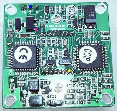
There are two convenient solder pads connected to pins 20 and 21 - they are marked in red in the picture below. Solder a wire so that it bridges the two pads, and solder another wire to the point marked in magenta below. For now you can simply connect the ends of these wires together. This will disable the automatic shutter - if you try the camera out under normal lighting you should get an overexposed picture. In dim lighting it should behave as normal.
Next you need to connect a wire to pin 2 of the CCD, marked in yellow. This carries one of the clock signals to the vertical shift register in the CCD. We need to be able to selectively disable the positive charge transfer pulses on this pin, which we achieve using a diode to shunt them to ground. I know it sounds harsh, but it works. Connect another wire to the ground connector (blue in the picture). Connect a diode to the pin2 wire, with the anode connected to pin 2. The anode is the end that doesn't have a stripe on it. For now, connect a switch between the cathode and the ground wire.
Again, inspect your work carefully, and then test it as follows: Open the switch on pin 2. Switch on the camera and dim the lights. You should see a dim image. Close the switch - the image should get dimmer, and if you look carefully you may see that it is made of alternate black lines. These lines are being integrated. Now open the switch and you should see a bright frame as the integrated lines are transmitted.
In order to generate all the lines of the image separately, do the following: Open the switch connected to pin 5, then close the switch connected to the CCD. Everything should be black, the CCD is integrating. Now close the pin5 switch and you should see a flash as half of the lines are transmitted. Open the pin 2 switch and you should see another flash as the remaining lines are transmitted. If you have a capture card, grab the two frames and load them into your favourite image processing program. You may need to move one or other frame down by one pixel, but if you add the two frames you should find you get a complete picture with 640x480 resolution. Wow! It may be a bit noisy - try zeroing out the 'black' lines if you can, to ensure they really are black.
Step Three - or - Back to step one