Modifications to the Camera PCB
The trickiest part of the whole modification is probably best done first, since it will be easier if the PCB is not cluttered with other wires. Also if it all goes horribly wrong you haven't wasted so much time!
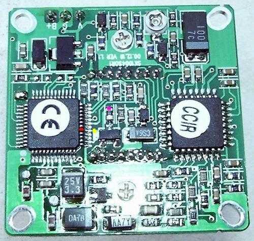
You need to identify the timing generator chip CXD2463R, on the rear of the circuit board. It is the smaller of the two square surface-mount chips, with the more closely packed legs. Of course.
Counting anticlockwise from the small circle on top of the chip, locate pin 5. This is marked with a red dot in the image below, and is the pin through which a +15V power supply is delivered to the chip. The first modification requires that this supply be switchable. I elected to lift the pin, which was rather fiddly. On subsequent examination it appears it may be possible to cut the track at the yellow spot instead, but I haven't confirmed this. Try it if you like!
Stop Press! Ray Schumacher has successfully used the track cutting technique, which is likely to be much easier than lifting the pin, and less likely to damage the camera. I have still not tried this method myself, but it has at least been validated. Many thanks, Ray!
The technique I used was to use a sewing pin as a lever and apply pressure outwards on the pin, whilst melting the solder on it. My soldering iron was a bit blunt, so I wrapped the leg from an old resistor round it and used the end of the leg as a narrower tip. It was still a bit big, but it did the job.
Once you've lifted the pin (or cut the track) you need to solder a wire to it. The best bet is to use thin, flexible multicore wire - say a strand of ribbon cable - and tease two strands from the multcore, snipping off the rest where the insulation ends. Twist the two strands together and apply some solder to them so that it wicks into the gaps between them. Then gently place the wire across the top of the square chip with the exposed strands touching the lifted pin. Apply the soldering iron and join the wire to the pin. Once you've made a good connection, epoxy the wire to the top of the chip and let it set. This will help prevent any accidental tugs from breaking off the pin - if that happens it is very hard to repair.
You now need to solder a wire to the location marked with a magenta spot in the image. (This location was connected via a track on the PCB to pin 5, which was just lifted up). It's probably worth epoxying this wire to the top of the chip as well, to be on the safe side. Remember that these wires will be at a potential of +15V, so you don't want them shorting onto anything! Check your soldering carefully, with a magnifier. Then check it again. Twice.
Once you've got these two wires soldered, you can test your work and actually produce a long exposure! Connect a switch between the wires and close it. Connect the camera to a video monitor (or PC running a suitable capture program, capable of showing 25fps - 30 in the US) and switch it on. You should see a normal video image - if not switch off and check your soldering even more carefully than before.
Once you've got a video signal, darken the room until the image is very faint. Then open the switch for a couple of seconds, and close it again. You should see blackness while the switch is open, followed by a single bright frame as you close it, followed by a normal video image again. The bright frame was a true integrated long exposure. Congratulations! The worst is over. Probably.
Step 2 - or - Previous step